In this tutorial, we will discuss the concept of interrupt, and how we could setup interrupt to free up from constantly polling the hardware resource and handling certain task in the "background".
This is part 3 of tutorials for ATtiny3227 AVR programming, focusing on bare metal programming, with ATtiny3227 as the target MCU.
What is Interrupt?
In digital computers, an interrupt is a request for the processor to interrupt currently executing code, so that the request event can be processed in a timely manner. If the request is accepted, the processor will temporarily suspend its current activities, save its state, and jump to a function called Interrupt Service Routine (ISR) to deal with the event. This interruption is often short and brief, allowing the software to quickly resume normal activities after the ISR finishes.
Interrupts are commonly used by hardware devices to indicate electronic or physical state changes that requires time-sensitive attention. Interrupts are also commonly used to implement computer multitasking and systems calls, especially in real-time computing.
Interrupts in Modern AVRs?
With modern AVRs, interrupts for various peripheral or system resource can be configured based on a "pre-defined" Interrupt Vector mapping table. An interrupt vector mapping table is a data structure that associates a list of ISRs for various peripherals. Each entry of the interrupt vector mapping table, called an Interrupt Vector, is the address of an ISR function. The vector table below shows the mapping of various interrupts for ATtiny 2-series (other Modern AVRs share similar vector table if not totally identical, always check the mapping table of specific MCU's datasheet).
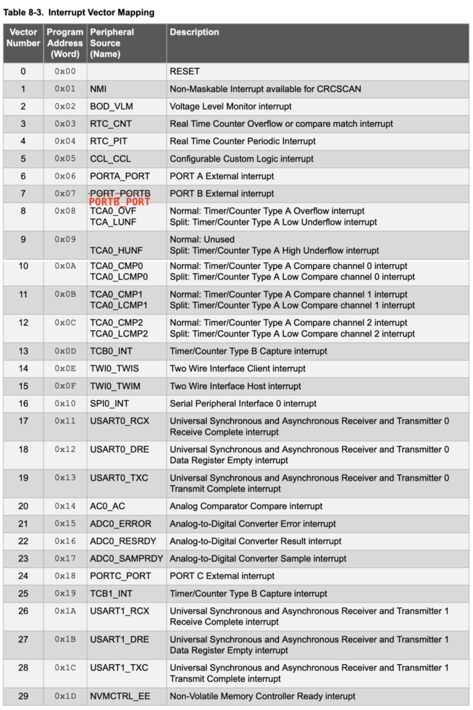
As shown in the table, there are total of 30 interrupt vectors for ATtiny 2-series. Notice that the each interrupt vector starts at an offset of 2 words (2 bytes for each word or 32-bit long in total). What it will hold is a single Jump instruction to actual ISR in the memory. For many peripherals, each of the interrupt vectors is connected to one peripheral instance, that is to say that any interrupt triggered by any pin of PORTA will share the same interrupt vector PORTA_PORT (0x0c). For some peripherals, it can have more interrupt sources for different operation modes, for example, there are two RTC vectors, one for RTC_CNT(0x06) for Real time counter overflow or compare match interrupt, and another for RTC_PIT(0x08) for real time counter periodic interrupt.
Also notice that the RESET interrupt has an address of $0000. This vector address is reserved for the main() function, that is, where the program started. During the compiler and linking process, the linker will set the RESET vector pointing to the address of main() function so that the program will started from the main() function.
Since there are 30 interrupts, it is possible that more than one interrupt event might occur at once, or at least, occur before the previous one is processed. The priority order is the sequence in which the processor checks for interrupt events. Therefore for higher the interrupt number in the list, the higher the priority. As per the interrupt vector table, RTC_CNT vector would have higher priority than PORTA_PORT vector.
Each interrupt signal input can be configured to be triggered by either a logic signal level (HIGH or LOW) or a particular level transition (Falling, Rising or both edges). Level-sensitive inputs continuously trigger interrupt requests so long as a particular (HIGH or LOW) logic level is applied to the peripheral. Edge-sensitive interrupts react to signal edges: a particular (rising or falling) edge will cause a service request to be triggered. The important part of edge triggering is that the signal must transition to trigger the interrupt. This contrasts with a level trigger where the LOW (or HIGH) level (depend on configuration) would continue to create interrupts until the signal returns to its default non-trigger level.
General Interrupt Setup Steps
Generally, in addition to the normal setup of a peripheral's registers, interrupt setup involved a few extra steps.
- Enable and configure a peripheral's interrupt.
- Write your ISR() function to handle the interrupt request event.
- Enable the Global Interrupt to allow interrupt to be triggered
An interrupt can be enabled or disabled by writing to the corresponding Interrupt Enable bit in the peripheral's Interrupt Control (peripheral.INTCTRL) register, or in the case of GPIO ports, the bits for controlling the interrupt trigger modes in the pin control register PORTn.PINxCTRL.
The ISR, the name might sound fancy, but it is nothing more than a part of the program (like a function) that executes once the interrupt is generated, excepts that ISR functions are a little special. They return nothing and so have no return type – not even void. And they take one parameter – a vector name identifying the port for which this function handles interrupts. The vector name is the name you see on the interrupt vector mapping table, adds with suffix _vect, the following skeleton shows two ISRs for PORTA interrupt and RTC Counter Overflow interrupt.
ISR(PORTA_PORT_vect) {
    // handle the PORTA interrupt event here
}

ISR(RTC_CNT_vest) {
    // handle RTC Counter Overflow event here
}
Notice that all the pins on PORTA (or on each GPIO PORT) will share one ISR vector, so when there are more than one pins within the same port setup the interrupt, additional checking is required within the function to determine which pin actually triggered the interrupt. We will further discuss this later when we talk about setting up ISR for PORTA.
When an interrupt request is triggered, the Interrupt Flag is set. For Modern AVRs, the interrupt request remains active until the Interrupt Flag is cleared. It is therefore usually for the ISR function to clear the Interrupt Flag within the ISR function so that the interrupt flag can be set again.
Note: An Interrupt Flag is set in the Interrupt Flags register of the peripheral (peripheral.INTFLAGS) when the interrupt event occurs, even if the interrupt is not enabled.
All those dry talk may sounds there are a lot to do to setup an interrupt, but it is actually quite simple, let's take a look at how to setup interrupt for GPIO.
GPIO Interrupt
In the GPIO tutorial, we demonstrated how to detect button (connected between Port A Pin0 and Ground)'s falling edge (through a debounce() function) and using it to turn on and turn off the LED blinking by constantly checking the GPIO input status of the pin. This "polling" method is kind of wasting MCU's resource because button press is a very infrequent event, but the MCU is polling the status in every single loop by constantly reading the PORTA.IN register. By using interrupt would free up the MCU time that could be used for other tasks. We will look into it on how we could use the interrupt to perform the same task (blinking LED based on button's toggled states).
#include <avr/io.h>
#include <util/delay.h>
#include <avr/interrupt.h>

volatile uint8_t buttonState = 1;

// ISR for PORTA, respond to interrupts on any pins on PORTA
ISR(PORTA_PORT_vect) {
    if (PORTA.INTFLAGS & PIN0_bm) {  // only if the interrrupt trigger is for PA0
        buttonState = !buttonState;  // toggle buttonState
        PORTA.INTFLAGS = PIN0_bm;    // clear PA0 interrupt flag
    }
}

int main() {

    _PROTECTED_WRITE(CLKCTRL.MCLKCTRLB, !CLKCTRL_PEN_bm);    // disable prescaler to run at 20MHz

    PORTA.DIRSET = PIN7_bm;            // Set only PA7(LED) as output without affecting other pins

    PORTA.DIRCLR = PIN0_bm;            // Set PA0 to input
    PORTA.PIN0CTRL = PORT_PULLUPEN_bm | PORT_ISC_FALLING_gc;    // Set PA0 to PULLUP with Interrupt sensing on Falling edge
    sei();

    while(1) {

        // LED blinking based on button state toggled by button ISR
        if (buttonState) {
             PORTA.OUTTGL = PIN7_bm;  // toggle LED
             _delay_ms(100);
        }
        else {
            PORTA.OUTCLR = PIN7_bm;  // turn off LED
        }

    }

    return 0;

}
One difference between the configuration of PIN0 from the previous "polling" code is that instead of simply enable the internal pull-up resistor, it further configure the ISC (Interrupt/Sense Configuration) bits within the PORTA.PIN0CTRL register with PORT_ISC_FALLING_gc. The ISC bits determines how a port interrupt can be triggered.
| Value | Name | Description |
|---|---|---|
| 0x0 | INTDISABLE | Interrupt disabled but input buffer enabled |
| 0x1 | BOTHEDGES | Interrupt enabled with sense on both edges |
| 0x2 | RISING | Interrupt enabled with sense on rising edge |
| 0x3 | FALLING | Interrupt enabled with sense on falling edge |
| 0x4 | INPUT_DISABLE | Interrupt and digital input buffer disabled |
| 0x5 | LEVEL | Interrupt enabled with sense on low level |
| other | — | Reserved |
A variable buttonState with a default value of 1 is used to track whether LED should be blinking (when buttonState is 1) or off (when buttonState is 0). The ISR() is called during the falling edge of the button press, and toggle the buttonState. The if (PORTA.INTFLAGS & PIN0_bm) ensures that we only handle the request coming from PIN0 instead of interrupts from other pins of PORTA, this is especially important when you have multiple interrupt setups for the same port.
Every time when the interrupt is triggered, the PORTA.INTFALGS register for the corresponding bit is set, and need to be reset by reading the register with PORTA.INTFLAGS = PIN0_bm.
The sei() is pre-defined in the avr-libc header file <avr/interrupt.h> for setting the Global Interrupt Enable bit in CPU.SREG. The sei() is not really a function but an assembly instruction SEI for setting the global interrupt bit. There is also another pre-defined macro which we didn't used here - cli() for clearing the Global Interrupt Enable bit to disable all the interrupts. We will discuss this in future when we encounter a use case for cli().
The infinite while loop now only contains the code for blinking LED and turn off LED based on the state of buttonState.
As you can see from the implementation, Using interrupt allows for infrequent button-press task to be executed in the "background" when they occur, without posing a run-time penalty of having to poll the hardware until the event occurs. This frees up our main loop to take care of the critical code, with the interrupt code pausing the main code to execute when the event of interest occurs. Using interrupt not only free up the resource for the MCU to do other tasks, in the case of GPIO interupt, the ability to set interrupt trigger mode make the code much simpler than the previous "polling" example.
Do's and Don'ts of ISR
When writing an Interrupt Service Routine (ISR) routine, there are a few things need to be aware
- Keep it as short as possible
- Don't use _delay_ms() or any blocking code
- Don't handle communication transaction within the interrupt
- Declare share resource with
volatile - Variables shared with main code may need to be protected when altering the value
The ISR should be kept as short as possible, it is often should only consists of the code to alter a variable that is used as a flag to indicated that interrupt has occured, and the main code will do something based on the flag. Likewise, don't use _delay_ms() or any blocking code within the ISR, as this will caused other interrupt not be able to enter the ISR if an interrupt occured during the blocking period. It should not handle the communication transaction within the ISR as well. As communication protocol, such as USART, I2C or even SPI, are sending data at much slower speed as compare to MCU clock ticks and those transactions often hold up the hardware resource during the transactions much longer.
The resource that alters by both main code and the ISR need to be declared with volatile. This tells the compiler that such variables might change at any time, and thus the compiler must reload the variable whenever you reference it, rather than relying upon a copy it might have in a processor register.
Strictly speaking, the
buttonStatein the code we shown previously is not necessary to be declared withvolatileas , we did so just in case if we eventually will add some code in the main where we might alter the flag.
In the following example where both the main and the ISR will alter the variable buttonPressed, and in this case, it should be declared with volatile.
volatile uint8_t buttonPressed = 0;

ISR(PORTA_PORT_vect) {
    if (PORTA.INTFLAGS & PIN0_bm) {
        buttonPressed = 1;  // set the value of buttonPressed
        PORTA.INTFLAGS = PIN0_bm;
    }
}

int main() {
    if (buttonPressed) {
        // do something
        buttonPressed = 0; // reset the value of buttonPressed
    }
}
There are cases where the shared resource/variable is a time-critical (such as timer counter) and are multi-byte data (for example, a uint32_t variable is 4-byte long) being updated by an ISR, then you may need to temporally disable interrupts when accessing such data to ensure data integrity, and you might want to copy the data to a different variable.
volatile uint32_t timeCount = 0;

ISR (RTC_PIT_vect) {
  timeCount++;
  RTC.PITINTFLAGS = RTC_PI_bm;
}

cli();
uint32_t currentCount = timeCount;  // get value set by ISR
sei();
Button Debounce with Interrupt
In the previous GPIO polling example, we uses a software debounce function to debounce the button state. When using button with interrupt, it is better to use hardware debounce by adding a 1uF (or other slightly larger value if necessary) in parallel to the button swith, this together with the internal pull-up resistor, formed a RC network which has a RC Time Constant that smooths out the glitches caused by the button bouncing activities. Without such hardware debounce circuit, it is not advisable to use interrupt with button as you won't get a reliable result due to the bouncing.
Interrupt is an important concept of any MCU. We will further explain various interrupt use cases in future tutorials.