
AThis tutorial will look into the USART controller within the ATtiny3227, and focus on setting up the serial USART on the Modern AVR platform.
This is part 4 of tutorials for ATtiny3227 AVR programming, focusing on bare metal programming, with ATtiny3227 as the target MCU.
All Modern AVR family lineup contains at least one USART hardware peripheral. USART is an acronym for Universal Synchronous and Asynchronous Receiver and Transmitter. The Modern AVR datasheet provides a list of supported features, including Full Duplex, Asynchronous and Synchronous operation; Half Duplex communication used in One-Wire mode and RS-485 mode, and even the supports for IrDA Compliant Pulse Modulation/Demodulation commonly used in remote control devices.
The USART hardware allows the AVR to transmit and receive data serially to and from other devices — such as a computer or another MCU. The block diagram shows the internal structure of USART module within the Modern AVR chips. The USART module has four pins, TX(transmit), RX(receive), XCK (clock) and XDIR (direction).
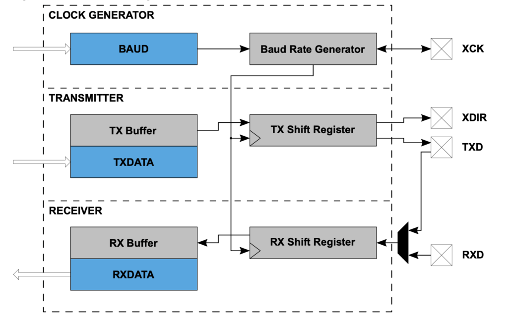
In Asynchronous mode, both RX and TX pins are used, thus achieving full-duplex communication. In One-Wire mode only, the TX pin is used for both transmitting and receiving in half-duplex operation. The XCK pin is used for clock signal in Synchronous mode, and the XDIR pin is only used in RS485 mode for direction control. We won’t be able to cover all of them in one tutorial, but we will focus on the most common use case for using as Asynchronous Communication and will cover other use cases in future.
Asynchronous Communication
Unlike other communication protocols such as I2C and SPI utilizing a bus data structure, the USART transmission system does not need a separate pin for the serial clock in asynchoronous communication. An agreed clock rate is preset into both devices, which is then used to sample the Receive and Transmit lines at regular intervals. Because of this, the USART often requires only two wires for bi-directional communication (Receive, Transmit) and a commond ground (GND).
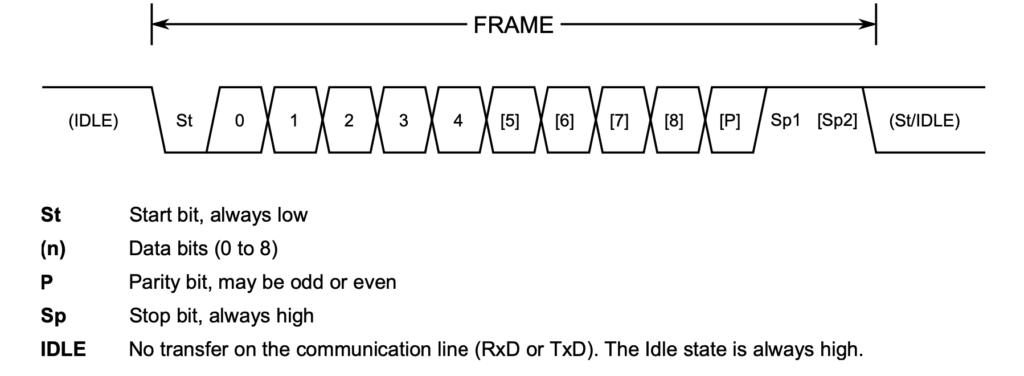
The USART data transfer is frame-based structure. A frame starts with a Start bit (St) followed by one character of data bits, varies from 5 to 9 bits depend on configuration. If enabled, the Parity bit (P) is inserted after the data bits and before the first Stop bit (Sp1 and/or Sp2).
In order to use the USART Asynchronous mode, it needs to be configured to the correct communication baud rate and frame format:
-
Configure the TXD pin as an output (and RXD as an input if necessary).
-
Set the frame format and mode of operation in USARTn.CTRLC.
-
Set the baud rate in USARTn.BAUD register.
-
Enable the transmitter (and the receiver if necessary) in USARTn.CTRLB.
The following code illustrates an asynchronous transmit-only USART configuration, with a frame operation format of 8-bit data, no parity check and 1 stop bit.
#include <avr/io.h>
#include <util/delay.h>
#include <stdio.h>

#define BAUD_RATE 115200UL

#ifndef USE_DEFAULT_TXD
#define USE_DEFAULT_TXD 1
#endif

static void USART0_init(uint32_t baud_rate, uint8_t default_txd) {

    if (default_txd)
        PORTB.DIRSET = PIN2_bm;                        // PB2 = TxD
    else {
        PORTA.DIRSET = PIN1_bm;                        // PA1 as TxD
        PORTMUX.USARTROUTEA |= PORTMUX_USART0_ALT1_gc; //map PA1 as alternative pin for TXD
    }

    USART0.CTRLC = USART_CMODE_ASYNCHRONOUS_gc | USART_PMODE_DISABLED_gc | USART_SBMODE_1BIT_gc | USART_CHSIZE_8BIT_gc;
    USART0.BAUD = (uint16_t) (F_CPU * 64 / (16 * (float) baud_rate) + 0.5);
    USART0.CTRLB |= USART_TXEN_bm;

}

static void USART0_sendChar(char c) {

    while (!(USART0.STATUS & USART_DREIF_bm)); //Wait for Data Register Empty Interrupt Flag is set
    USART0.TXDATAL = c;

}

int main(void) {

    _PROTECTED_WRITE(CLKCTRL.MCLKCTRLB, !CLKCTRL_PEN_bm); // clear Prescaler to run at 20MHz
    while (!(CLKCTRL.MCLKSTATUS & CLKCTRL_OSC20MS_bm)) {};

    USART0_init(BAUD_RATE, USE_DEFAULT_TXD);

    while (1)
    {
        char str[] = "Hello World\n";
        for (size_t i=0; i< strlen(str); i++) {
            USART0_sendChar(str[i]);
        }
        _delay_ms(500);
    }

    return 0;
}
Step 1 - Configure TX pin
The TX pin must be configured as output. What port and pin should be used as TX pin varies from chip to chip and can be found from the datasheet of the chip, under the "PORT Function Multiplexing" table of ATtiny3217 datasheet. Each USART has two sets of pin positions - the default and alternate pin positions.
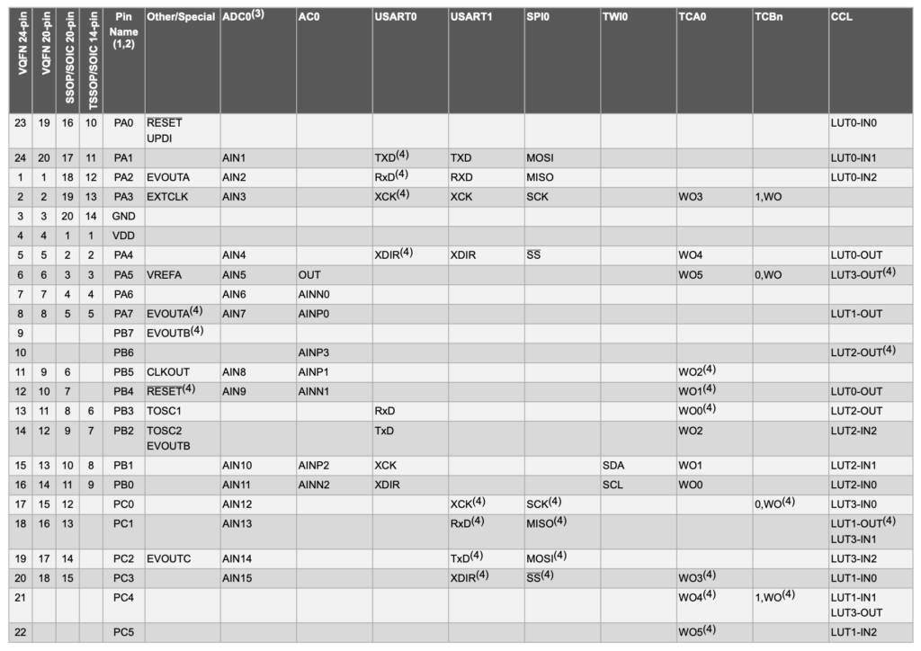
The "Port Function Multiplexing" table is an important table for bare metal programming, it provides the information of each pin's capability and functionality when the pin is configured for various purpose. We often need to come back to this table whenever we need to configure a peripheral.
The Port Function Multiplexing table indicates that the TX pin(TXD) for USART0 is default to PB2 but can also be re-mapped to the alternative pin at PA1. We configure the PB2 as the TxD by setting it as an OUTPUT pin. However, in case we want to use the alternative pin PA1 as TXD, PORTMUX register need to be configured to rout the pin from PB2 to PA1:
    if (default_txd)
        PORTB.DIRSET = PIN2_bm;                        // PB2 = TxD
    else {
        PORTA.DIRSET = PIN1_bm;                        // PA1 as TxD
        PORTMUX.USARTROUTEA |= PORTMUX_USART0_ALT1_gc; //map PA1 as alternative pin for TXD
    }
Step 2 - Set UART Frame Format
The USART0.CTRLC register determines the USART frame format and operation mode, it has a reset default value of 0x03, which according the datasheet, it means that when the MCU is power-up, it is set to Asynchorous mode, 8-bit data, no parity bit, and 1 stop bit, this is exactly what we want, so technically, we don't need to explicitly configure the register due to this default value, but we do it explicitly to make our intention clear.
USART0.CTRLC = USART_CMODE_ASYNCHRONOUS_gc | USART_PMODE_DISABLED_gc | USART_SBMODE_1BIT_gc | USART_CHSIZE_8BIT_gc;USARTn.CTRLC register
| Bit | CMODE[1:0 | PMODE[1:0] | SBMODE | CHSIZE[2:0] | ||||
|---|---|---|---|---|---|---|---|---|
| Reset | 0 | 0 | 0 | 0 | 0 | 0 | 1 | 1 |
-
Bits 7:6 – CMODE[1:0] USART Communication Mode
Value Name Description 0x00 ASYNCHRONOUS Asynchronous USART 0x01 SYNCHRONOUS Synchronous USART 0x02 IRCOM Infrared Communication 0x03 MSPI Host SPI -
Bits 5:4 – PMODE[1:0] Parity Mode
Value Name Description 0x00 DISABLED Disabled 0x01 EVEN Enabled, even parity 0x02 ODD Enabled, odd parity -
Bit 3 – SBMODE Stop Bit Mode
Value Description 0x00 1 Stop bit 0x01 2 Stop bits -
Bits 2:0 – CHSIZE[2:0] Character Size
Value Name Description 0x00 5BIT 5 data bits 0x01 6BIT 6 data bits 0x02 7BIT 7 data bits 0x03 8BIT 8 data bits 0x04 - Reserved 0x05 - Reserved 0x06 9BITL 9 data bits (lower byte) 0x07 9BITH 9 data bits (higher byte)
Step 3 - Set Baud Rate
The baud rate refers to the number of bits to be sent per second. The higher the baud rate, the faster the communication. Common baud rates are: 1200, 2400, 4800, 9600, 19200, 38400, 57600 and 115200 and even higher baud rate, with 9600 and 115200 being the most commonly used one. ATtiny3227 datasheet provides the necessary formula for calculating the value that need to use for setting the USART0.BAUD register at various baud rates.
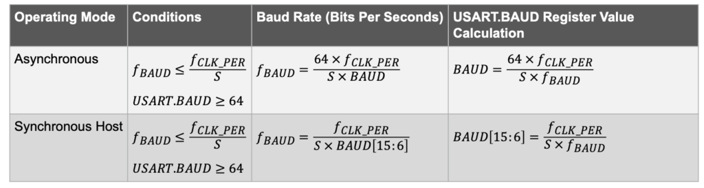
The fCLK_PER in our case is the F_CPU value that we set in the Makefile, the S is the sampling rate, in Asynchronous operating mode, it is 16 (NORMAL mode) or 8
(Double-speed mode). The fBaud is the baud rate we want to configure the USART for. This formula translate into code as:
USART0.BAUD = (uint16_t) (F_CPU * 64 / (16 * (float) baud_rate) + 0.5);The 0.5 at the end of the formula ensure that the value get round-up to the nearliest integer value to be used for the USART0.BAUD register. Giving that our ATtiny3227 have a clock speed F_CPU of 20MHz, if the baud_rate is 115200, the USART0.BAUD would need to set to 695 (or 0x2B7), and if the baud_rate is 9600, the USART0.BAUD would be set to 8334 (or 0x208E).
Step 4 - Enable USART Transmitter
Each USART module's transmitter and receiver can be enabled independently based on the application needs. For now, we only want to send messages instead of receiving messages, so we only enable the transmitter.
USART0.CTRLB |= USART_TXEN_bm;As shown in the block diagram at the beginning of this tutorial. The USART transmitter sends data by periodically altering the TXD line bit-by-bit on every clock cycle of the baud rate generator output. The data transmission is initiated by loading the Transmit Data USARTn.TXDATAL (if the data is less than or qual to 8-bit) and USARTn.TXDATAH (if data-bit is set to 9-bit) registers with the data to be sent. The data in the Transmit Data registers are moved to the TX Buffer once it is empty and onwards to the Shift register once it is empty and ready to send a new frame. After the Shift register is loaded with data, the data frame will be transmitted.
USARTn.STATUS register
| Bit 7 | Bit 6 | Bit 5 | Bit 4 | Bit 3 | Bit 2 | Bit 1 | Bit 0 |
|---|---|---|---|---|---|---|---|
| RXCIF | TXCIF | DREIF | RXSIF | ISFIF | Reserved | BDF | WFB |
-
Bit 7 – RXCIF USART Receive Complete Interrupt Flag
This flag is set when there are unread data in the receive buffer and cleared when the receive buffer is empty. -
Bit 6– TXCIF USART Transmit Complete Interrupt Flag
This flag is set when the entire frame in the Transmit Shift register has been shifted out, and there are no new data in the transmit buffer (TXDATAL and TXDATAH) registers. It is cleared by writing a ‘1’ to it. -
Bit 5 – DREIF USART Data Register Empty Interrupt Flag
This flag is set when the Transmit Data (USARTn.TXDATAL and USARTn.TXDATAH) registers are empty and cleared when they contain data that has not yet been moved into the transmit shift register.
Refer to datasheet for the definition of rest of status bits
The Transmit Data registers can only be re-loaded when the Data Register Empty Interrupt Flag (the DREIF bit) in the USARTn.STATUS register is set, indicating that they are empty and ready for new data. Therefore before sending any data, we need to check the DREIF bit before writing a data to the USARTn.TXDATA register.
static void USART0_sendChar(char c) {

    while (!(USART0.STATUS & USART_DREIF_bm)); // Wait if Data Register Empty Interrupt Flag is not set
    USART0.TXDATAL = c;

}
In order to send a string of characters such as "Hello World\n", it is need to loop through the string character-by-character and calling USART0_sendChar() function repeatly.
Setting up Serial Terminal
There are many ways to access a serial port, SparkFun has a great introduction of Serial Terminal Basics which discusses all kind of Serial Terminal applications for various operating system environments. Pick the one that suit you. Personally, I'm using CoolTerm because it works for MacOS. If you have Arduino IDE installed on your PC, you could use the Serial Monitor as your Serial Terminal as well.
Setting up printf() for AVR
In C, we often use printf() function which is part of the stdio.h library to print some data to screen. printf stands for "print formatted". printf can take variables from memory and print them to a data stream defined in the library. To define a stream for printf, we create a USART_stream using a pre-defined system macro like this:
static FILE USART_stream = FDEV_SETUP_STREAM(USART0_sendChar, NULL, _FDEV_SETUP_WRITE);In the nutshell, this macro create a USART_stream which tell the sytem where to put(send) data, and where to get data for the data stream. We named our data stream as USART_stream and we are telling the stream handler to uses our USART0_sendChar function for putting data into the stream. The USART0_sendChar function for steram needs to be modified as it has different function prototype than our original USART0_sendChar() function, in addition to the character to be sent as the function parameter, it is expecting a pointer to the stream and return an integer value. Finally, we need to change our USART0_init function to point the stdout stream to our defined USART_stream.
#include <avr/io.h>
#include <avr/interrupt.h>
#include <util/delay.h>
#include <stdio.h>

static int USART0_sendChar(char c, FILE *steam) {
    while (!(USART0.STATUS & USART_DREIF_bm)); // Wait for Data Register Empty Interrupt Flag is set
    USART0.TXDATAL = c;

}

static FILE USART_stream = FDEV_SETUP_STREAM(USART0_sendChar, NULL, _FDEV_SETUP_WRITE);

static void USART0_init(uint32_t baud_rate, uint8_t default_txd) {

    if (default_txd)
        PORTB.DIRSET = PIN2_bm;                        // PB2 = TxD
    else {
        PORTA.DIRSET = PIN1_bm;                        // PA1 as TxD
        PORTMUX.USARTROUTEA |= PORTMUX_USART0_ALT1_gc; //map PA1 as alternative pin for TXD
    }

    USART0.CTRLC = USART_CMODE_ASYNCHRONOUS_gc | USART_PMODE_DISABLED_gc | USART_SBMODE_1BIT_gc | USART_CHSIZE_8BIT_gc;
    USART0.BAUD = (uint16_t) (F_CPU * 64 / (16 * (float) baud_rate) + 0.5);
    USART0.CTRLB |= USART_TXEN_bm;

    stdout = &USART_stream;

}

int main(void) {

    _PROTECTED_WRITE(CLKCTRL.MCLKCTRLB, !CLKCTRL_PEN_bm); // clear Prescaler to run at 20MHz

    USART0_init(BAUD_RATE);

    while (1)
    {

        char str[] = "Hello World\n";

        printf("%s", str);
        _delay_ms(500);
    }

    return 0;
}
We no longer need to manually loop through the string to send character-by-character to the USART0_sendChar function, We can now use the printf function to send some data string to the screen.