One of my long-waiting outstanding projects is to fix this no-frill SoundTech doorbell. I finally done it, by replacing the RF transmitter/receiver used by the doorbell with ESP-NOW.
The Problem with SoundTech doorbell
The doorbell is a wireless one, operated on a unknown frequency band, presumably on 403MHz band or even 27MHz band. The indoor unit (the receiver unit) was damaged due to battery leak of Alkaline batteries. I could simply buy some replacement battery contacts from Aliexpress and be done with it. But that doesn't guaranteed it won't be damaged by Alkaline battery again in future. Replacing battery every 6 months or so is also quite annoying, although this can easily be fixed by using re-chargeable NiCad batteries or with a AC/DC power adaptor.
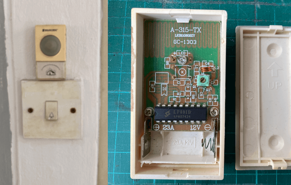
The outdoor unit (the transmitter) is a stick-to-the-wall type of device with a double-side tape on the back that sticked to the wall, and it used a A23 (or 23A) 12-volt battery, although it has much longer battery life than the indoor unit. The double-side tape sometime wear-off aftr a few time of battery replacements, I have to put in the new double-side tape or it will sometime fall onto the ground as the tape no longer be able to hold it on the wall. It is another source of the annoying for this door bell.
So I want to fix all this so that:
- I don't need to replace the battery often, and
- definitely no Alkaline battery, ever;
- No stick-to-the-wall type of outdoor unit;
- Uses the in-wall rocker switch that come with the building construction to host the outdoor unit.
The Idea
When I first time exploring ESP-NOW a few years ago, I felt that ESP-NOW would be a perfect protocol for doorbell application. The outdoor unit would be an ESP-NOW transmitter that can send a signal whenever the doorbell button is pressed, and can then go into deepsleep mode so that it consumed literally almost no power other than during the awake time which should be very briefly in milli-seconds.
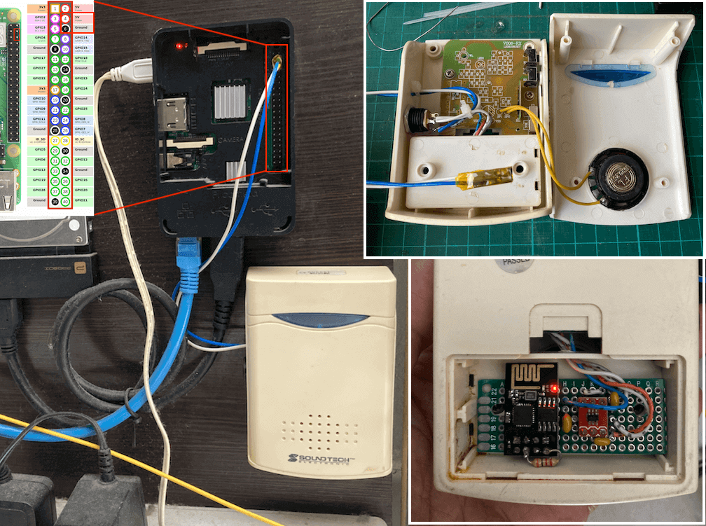
The indoor unit, i.e. the receiver, need to be constantly powered. I have an Raspberry Pi 3 used as a web server that hosting this website and running 24-by-7. The ESP-NOW receiver can therefore connect to the power supply of the Raspberry Pi. Problem solved, at least for the power supply. However, in order to play a melody, I would need a .wav or .mp3 file that generate the tone, then I would need a audio amplifier like LM386 to amplify the audio signal. That's seems to be a lot of extra circuitry and probably need a custom PCB shield to be sit on top of the Raspberry Pi, and I don't have a LM386 with me back then, so the project was put aside for the past several years.
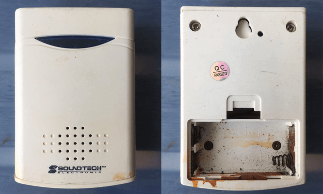
SoundTech Indoor Unit Hack
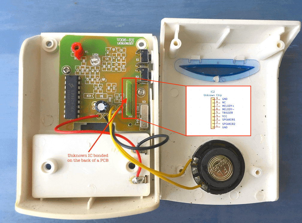
The SoundTech Doorbell consists of a dozen of melodies and produed a decent level of sound with a merely 0.25W 16-ohm speaker. I recently decided to take a deep look into the circuitry by doing some reversed-enginnering to see if I could utilize part of the circuitry and the casing for my new ESP-NOW door bell. The indoor unit basically consists of some discrete components that form the RF front-end receiver and then feed into an IC named LP8029-M4, all the discrete components had the silk screen printed on top of the PCB, but all the components are soldered on the copper side of the PCB, except for a few through-hole components like the ICs and switches. A little bit of reverse-engineering shows that the output of LP8029-M4 is feeded into an unknown IC which is bonded on a small piece of a PCB. This unknown IC has a 9-pin PCB-edge interface, it is some sort of a melody generator plus MCU, it take the signal decoded from RF signal as the trigger to generate the doorbell melogy, there are two pins that connected to two tactile buttons that serve as UP and DOWN selection of different melodies. The chip must have an internal amplifier as it has two output pins that direct connect to the speaker, via a SP3T switch (and two resistors) for selecting LOW, MEDIUM, and HIGH volume.
I de-solder this unknown chip and powered it with an external 3V power supply (and eventuall 3.3V to see if it would work at 3.3V, and it does), sure enough, I'm be able to triggger the chip with a pulse on the input trigger pin (pin 5) to generate a melogy, or select a melody as expected through two tactile switches connected between Ground and pin 6 and 7 with two external pull-up resistors. This is great, that's means that I can re-use this chip instead of going through the trouble to generate my own .wav or .mp3 sound and I also don't need an extra audio amplifier chip.
Implementation
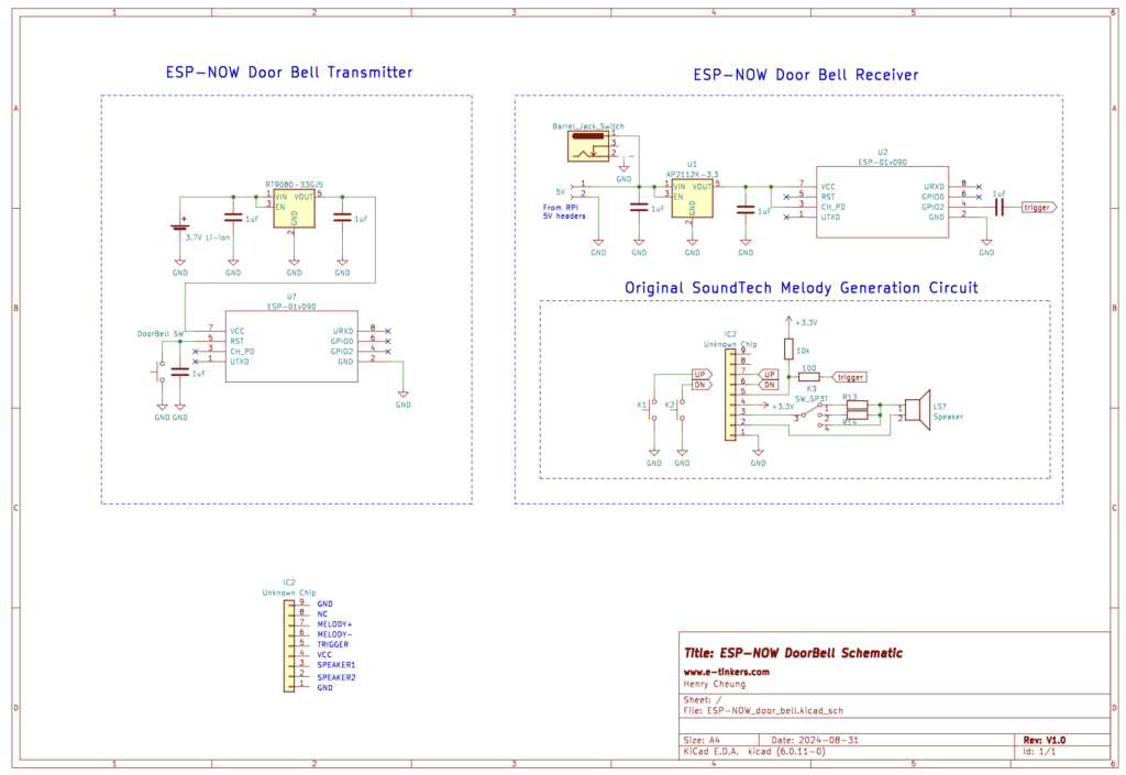
I have a few ESP-01 modules with me and the small form factor seems to be perfect for this application. The Outdoor ESP-NOW unit simply consists of an ESP-01 with a LDO and a Li-Ion battery. I choose RT9080 LDO for 1) I have a few with me; but more importantly 2) it has very low quiescent current of 2uA which is good for reducing the power leakage during long deep sleep time of ESP-01. As the ESP-01 module does not break out the GPIO16 which is generally required for waking up ESP8266 MCU from deep sleep, so I simply connect the door bell button to RST pin of ESP-01 module which basically reset the ESP8266 when the switch is pressed.
For the EPS-NOW Receiver, another ESP-01 is used to decode the received message, when a message is received from the ESP-NOW Transmitter, it generates a pulse on GPIO2 which is connected to the unknow IC via a 1uF capacitor to trigger the melody as shown in the schematic below.
I purchased a new in-wall doorbell button to replace the old one and cut a tiny piece of prototype PCB to hold the RT9080 LDO and ESP-01 module on the back of the button switch. I have both 1000mAh and 2900mAh Li-Ion batteries with me, althought the power consumption during ESP-NOW transmission consumed 72-84mA during transmission when the ESP-01 running at 80MHz (I did not running the ESP-01 at 160MHz as it is not necessary), but the total period of wake-up time is about 105 milli-seconds, the rest of the time the ESP-01 would be in deep-sleep mode, so the overall circuitry including ESP8266 and the LDO consumed a total of 25uA. With the 1000mAh battery, it would estimated last for 1204 days (i.e. more than 3 years), and the 2900mAh battery would last for 3373 days! (i.e. more than 9 years!). I decided to use the 2900mAh battery because I have plenty of it with me.
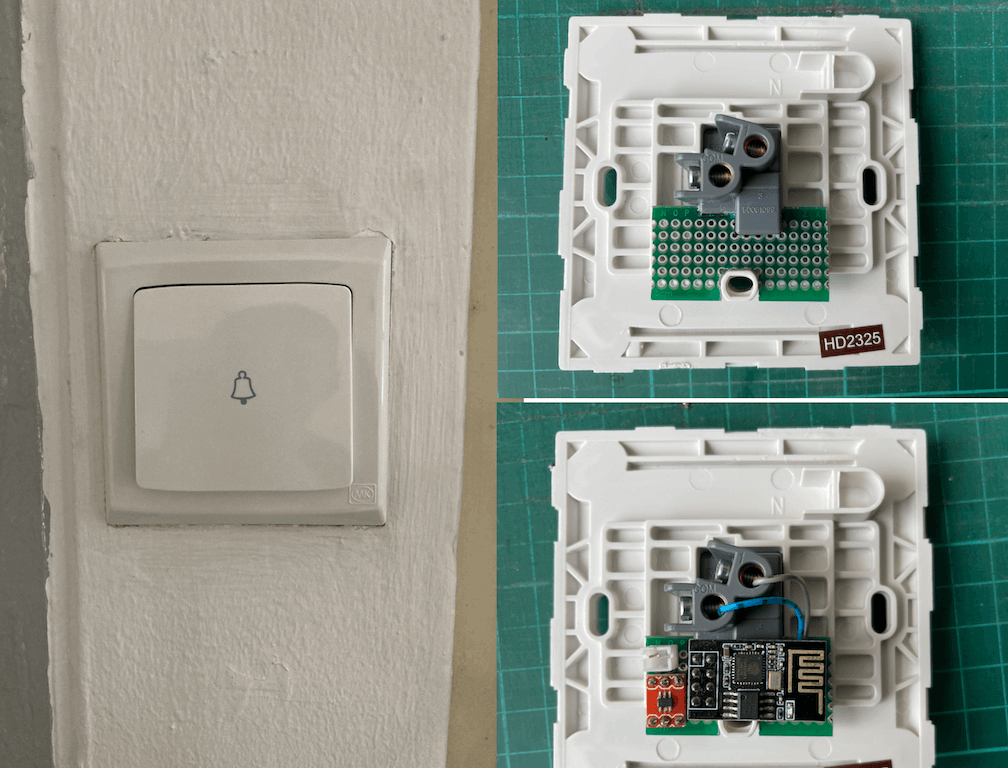
For the ESP-NOW Receiver (i.e. the indoor unit), I decided to utilize the original SoundTech Doorbell casing, and clean up the AA battery compartment and use it to host a tiny protoboard for an AP2112 3.3V LDO and ESP-01. I also decided to solder the unknown IC back to where it was on the original PCB, and de-solder all the unnecessary components of the original RF front-end but kept the components related to the unknown IC. This allows me to utilize the original casing of SoundTech doorbell receiver. The power is taken from the 5V rail from the nearby Raspberry Pi via Dupont jumper wires, I decide to add a barrel jack in parallel as 5V input in case in future if I would want to power the doorbell with a separate wall power adaptor.
The Software
The software for the transmitter (outdoor unit) is very simply and straigthforward. When the ESP-01 is powered up (or reset by the rocker switch connected to the RST pin), it will set the WiFi to the station mode and disconnected from WiFi as required by ESP-NOW protocol, if esp_now_init() is successful, it will then setup itself as the role of controller (i.e. transmitter) and add the receiver as a peer, registered the callback function and then send a "command", in this case, the "command" is just an arbitrary character "^" I decided to use. The call back function is triggerred when the command is sent, the callback function simply put the ESP-01 to deep sleep mode which will only wake-up by a button interrupt.
ESP-NOW Transmitter
// ESP-01_doorbell_transmitter.ino

#include <ESP8266WiFi.h>
#include <espnow.h>

//#define _DEBUG
#define RETRY_INTERVAL 5000e6   // Retry interval = 5 seconds

// the following three settings must match the slave settings
uint8_t remoteMac[] = {0x82, 0x88, 0x88, 0x88, 0x88, 0x88};
const uint8_t channel = 14;
uint8_t command = 0x5e;   // char '^'

void sendCallBackFunction(uint8_t* mac, uint8_t sendStatus) {
#ifdef _DEBUG
  Serial.printf("< Device: %02x:%02x:%02x:%02x:%02x:%02x\n", mac[0], mac[1], mac[2], mac[3], mac[4], mac[5]);
  Serial.printf("< Status: %s\n", (sendStatus == 0 ? "Success" : "Failed"));
#endif
  ESP.deepSleep(0);    // only wake up by button interrupt
}

void setup() {

#ifdef _DEBUG
  delay(1000);
  Serial.begin(74880);
  Serial.println();
  Serial.println("ESP-Now Transmitter");
  Serial.printf("Transmitter mac: %s \n", WiFi.macAddress().c_str());
  Serial.printf("Receiver mac: %02x:%02x:%02x:%02x:%02x:%02x\n", remoteMac[0], remoteMac[1], remoteMac[2], remoteMac[3], remoteMac[4], remoteMac[5]);
  Serial.printf("WiFi Channel: %i\n", channel);
#endif

  WiFi.persistent(false);
  WiFi.mode(WIFI_STA); // Station mode for esp-now controller
  WiFi.disconnect();

  if (esp_now_init() != 0) {
#ifdef _DEBUG
    Serial.println("ESP_Now init failed...");
#endif
    ESP.deepSleep(RETRY_INTERVAL);    // restart after sleep
  }

  esp_now_set_self_role(ESP_NOW_ROLE_CONTROLLER);
  esp_now_add_peer(remoteMac, ESP_NOW_ROLE_SLAVE, channel, NULL, 0);
  esp_now_register_send_cb(sendCallBackFunction);
  esp_now_send(remoteMac, &command, 1);
}

void loop() {

}
The software for the Indoor ESP-NOW receiver set itself to WIFI_AP mode as required by the ESP-NOW protocol, GPIO2 is used as the DOORBELL pin and configured as OUTPUT for generating the pulse to trigger the melody. A self-adminstrated MAC address is used instead of the ESP-01's hardware MAC address, this provided the advantage that you could replace an ESP-01 without the need to modified the transmitter and receiver code to match the hardware MAC address. A callback function is called when the ESP-01 received a message from the ESP-NOW transmitter, it then generate a pulse on pin DOORBELL to trigger the melody generator on the Unknown IC.
// esp-01_doorbell_receiver.ino
#include <ESP8266WiFi.h>
#include <espnow.h>

#define _DEBUG
#define RETRY_INTERVAL 5000
#define DOORBELL 2

// the following 3 settings must match transmitter's settings
uint8_t mac[] = {0x82, 0x88, 0x88, 0x88, 0x88, 0x88};
const uint8_t channel = 14;
uint8_t command;

void receiveCallBackFunction(uint8_t *txMac, uint8_t *command, uint8_t len) {
#ifdef _DEBUG
  Serial.printf("> From: %02x:%02x:%02x:%02x:%02x:%02x\n", txMac[0], txMac[1], txMac[2], txMac[3], txMac[4], txMac[5]);
  Serial.printf("> Cmd:  %c Len:%d\n",(char) *command, len);
#endif
  digitalWrite(DOORBELL, LOW);
  delay(10);
  digitalWrite(DOORBELL, HIGH);

}

void setup() {
  WiFi.persistent(false);
  WiFi.mode(WIFI_AP);
  WiFi.disconnect();
  wifi_set_macaddr(SOFTAP_IF, mac);

  pinMode(DOORBELL, OUTPUT);
  digitalWrite(LOW);

#ifdef _DEBUG
  delay(1000);
  Serial.begin(74880);
  Serial.println();
  Serial.println("ESPNow Receiver");
#endif
  if (esp_now_init() != 0) {
     delay(RETRY_INTERVAL);
     ESP.restart();
  }
  esp_now_set_self_role(ESP_NOW_ROLE_SLAVE);
  esp_now_register_recv_cb(receiveCallBackFunction);
}

void loop() {

}